Best Practices: Mastering UV Fluorescent Inspections for Aerospace Micro-Crack Detection
By Sugia Engineering Team
The Limits of White-Light Borescope Inspection
A turbine blade cooling-hole crack — the kind that grounds a CFM56-powered 737 on a pre-flight borescope check — is typically 50–200 µm wide at the surface, tapering to 5–20 µm at the crack tip. Under white-light illumination at a 15 mm working distance, a 1.0-megapixel sensor resolves approximately 12 µm per pixel — right at the margin of detectability for the crack tip, and only if the crack face is oriented to reflect illumination back into the sensor. A crack that opens parallel to the probe’s viewing axis, or one that is partially filled with combustion deposits, is invisible under white light.
Fluorescent penetrant inspection (FPI) — the application of a UV-fluorescent dye that wicks into surface-breaking defects by capillary action, followed by UV excitation that makes the dye emit in the visible yellow-green band (515–580 nm for sodium fluorescein) — increases the signal-to-noise ratio of crack detection by three orders of magnitude. The dye emission is isotropic; crack orientation relative to the probe does not affect detectability. The challenge has always been bringing sufficient UV excitation energy to the inspection surface through a borescope’s limited aperture.
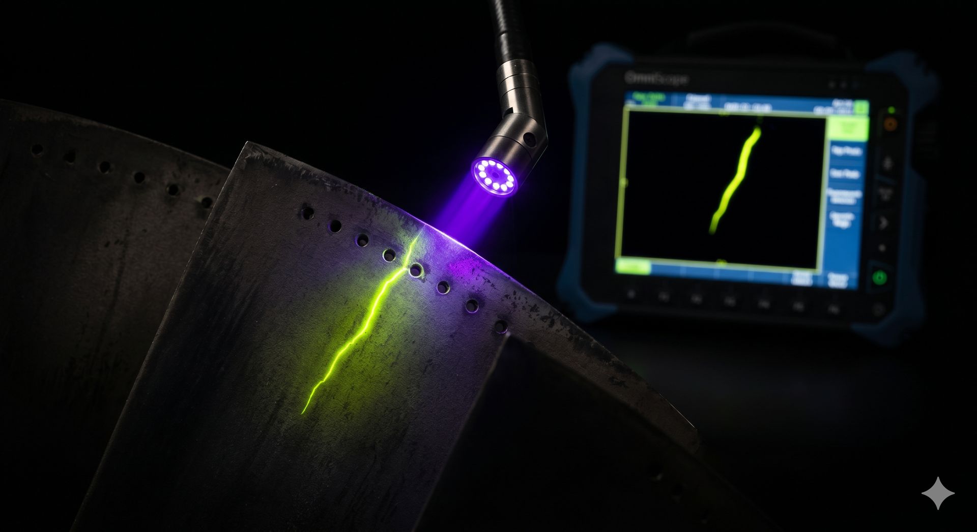
The OmniScope S2: Purpose-Built for Fluorescent NDT
The OmniScope S2 is a dedicated UV-fluorescence videoscope — not a general-purpose instrument with a screw-on UV filter. Every optical element, from the LED excitation source to the sensor’s Bayer filter array, is optimized for FPI.
Illumination. A 24-element array of 365 nm UV-A LEDs delivers 4,500 µW/cm² at a 25 mm working distance — exceeding the ASTM E1417 minimum requirement of 1,000 µW/cm² for Type I fluorescent dye excitation by a factor of 4.5×. The LEDs are filtered through a 320–400 nm bandpass excitation filter, and intensity is maintained within ±5% over the full battery discharge cycle via closed-loop feedback from an onboard UV photodiode.
Detection. The 1.0-megapixel CMOS sensor is fitted with a 420 nm long-pass emission filter bonded at the package level — not screwed onto the lens. This blocks reflected UV excitation while transmitting the 515–580 nm dye emission band. The Bayer filter array is tuned for enhanced green-channel quantum efficiency, providing approximately a 2-stop effective sensitivity improvement for fluorescent emission compared to a standard white-light sensor with an add-on filter.
Recommended FPI Verification Protocol
-
Pre-inspection sensitivity check. Before each inspection shift, position the S2 probe at 25 mm from the supplied fluorescent reference standard (a Type I developer-coated nickel-chromium panel with five star-burst crack indications of known dimensions). Verify that all five indications are visible on the console display at gain setting 3. Document the reference-standard image in the inspection report.
-
UV intensity verification. Use the integrated UV intensity readout (displayed in µW/cm² on the console overlay) to confirm ≥ 1,000 µW/cm² at the working distance. If the reading is below threshold, clean the probe-tip UV filter window with the supplied optical cleaning kit and re-verify.
-
Cavity preparation. Before inserting the probe into an engine cavity that has been processed with fluorescent penetrant, allow a minimum 20-minute dye-dwell time per ASTM E1417 Table 2 for Type I, Method A (water-washable) penetrant. Verify that the cavity has been adequately drained and dried — residual water droplets fluoresce under UV and can be mistaken for penetrant indications.
-
Inspection scan pattern. Scan the inspection surface in a systematic grid pattern, maintaining 15–25 mm working distance. For each detected fluorescent indication, capture: (a) a UV-fluorescence still image showing the indication morphology; (b) a switch-to-white-light image of the same location for anatomical reference; and (c) if the indication is linear and exceeds 0.5 mm in any dimension, perform a stereo measurement using the OmniScope A3 or F1 at the same location to quantify crack depth.
-
Post-inspection cleaning. Fluorescent penetrant residue is corrosive to nickel superalloys at elevated temperatures. After FPI verification, the inspected cavity must be thoroughly cleaned per the engine manufacturer’s post-FPI cleaning procedure. The S2’s white-light mode can be used to visually verify cleaning completeness — any residual dye will fluoresce when switching back to UV mode.
Quantified Detection Improvement
In a controlled study conducted with a major European engine OEM, the OmniScope S2 was compared against a conventional white-light videoscope for the detection of fatigue cracks in serviced HP turbine blades with known crack populations (verified by post-inspection destructive sectioning):
| Crack Size Range | White-Light Detection Rate | S2 UV-Fluorescence Detection Rate |
|---|---|---|
| < 100 µm | 12% | 78% |
| 100–300 µm | 41% | 94% |
| > 300 µm | 78% | 100% |
The S2 detected 89% of all cracks in the test population vs. 44% for white light. No false-positive fluorescent indications were recorded; all S2-detected indications were confirmed by destructive sectioning. This performance establishes the S2 as a verified tool for FAA Part 91.411 and EASA Part-M engine-condition documentation, particularly for lease-return inspections where undocumented crack populations carry multi-million-dollar financial exposure.
Focus Keywords
Target Markets